Welcome!


Reci Power Supply / Power Source for 90 - 100W Z2 / S2 CO2 Laser Tube, 110V
Update time:2022-03-09 03:22:22
Price:Negotiable
Min Order:1 Set / Sets
- T/T MoneyGram Credit Card PayPal
- tianjin/shanghai/guangzhou
- 0 per Month
Basic Info
| After-sales Service Provided | Overseas service center available | Brand Name | SIC | Certification | CE |
|---|---|---|---|---|---|
| Condition | New | Model Number | CS-PS-DY10-110V | Place of Origin | China |
| Warranty | one year | ||||
Product Description
Product Description
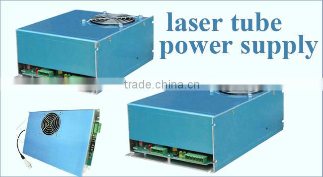
Mark & model: DY10, small size, quick response, it is suitable for Reci Z2/S2 laser tube.
Origin: Asia and Pacific Area China
Quality standard: International
H.S. Classification: Machinery & Electronics Electr. Element 8541 Semiconductor devices; light - emitting diodes parts.
Warm tips:
The power supply is to be used for Reci, EFR and WEEGIANT laser tube. If you want to make it work on other brands, please check the specification before order.
Warm tips:
The power supply is to be used for Reci, EFR and WEEGIANT laser tube. If you want to make it work on other brands, please check the specification before order.
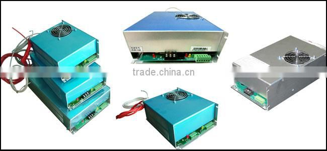
Features:
This power supply / power source adopts thin type design. The shape of this power supply / power source is thin which is specially designed for special laser tube.
The power supply / power source makes laser tube output larger and more stable.
The power supply / power source makes laser tube output larger and more stable.
Quick Response: It can enlarge laser power and prolong laser tube‘s service life.
Easy Control: The start and stop of laser can be easily controlled by TTL level.
This power supply / power source has output open circuit protection.
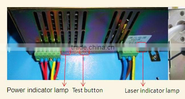
This power supply / power source has TTL signal indication, water through signal indication and laser output indication.
This power supply / power source has the BUTTON to test it work properly.
Application: Sculpture and cut acrylic, fabric, double color sheet and rubber, etc
We stick the protection film on the power source to prevent the metal parts of the scrape!

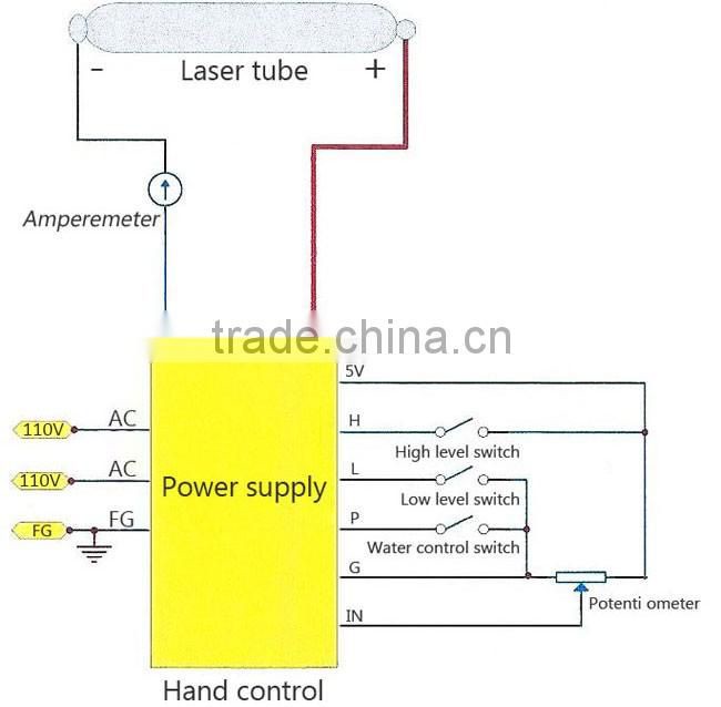
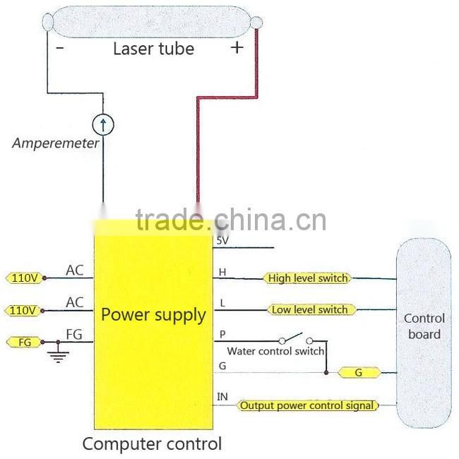

1) Footer 1 is 5V power supply / power source. (Not needed when connecting the cardinal plate. It is used when regulating the power with potentiometer and the 5V current should be less than 10 mA.
2) TH. TL refers to high and low power level respectively, and WP refers to water protection.
3) Footer 5 G refers to ground and 6 refers to input end.
4) When connecting the control plate, connect the light signal with footer 2 in the case of high power level light-emitting, (footer 3 for low power level light-emitting), connect the ground-wire with footer 5, connect footer 6 with power control analog signal, and make short circuit for footer 4 and 5.
5) PWM can also be used in footer 6, but the pulse peak is required to reach 5V, and the frequency should be above 20K.
6) For testing: 3, 4 and 5 are in short circuit (or 4, 5 are in short circuit and 3, 5 are connected to switch), the potentiometer center is connected with 6 IN, and the two other ends are connected to 5V and ground (1 and 5) respectively.
7) The high power level controls the light, 1 and 2 are connected, and 4 and 5 are in water protection.
8) It is not proposed to control laser power with high-frequency modulation, because it will have impact on the service life of the laser.
9) The model is applicable to Z2/S2 laser, it is necessary to regulate and use the current according to the laser instructions.
10) The ammeter is concatenated to the cathode line.
II. Instruction for power wire

Note: The table 10A refers to the connection wire requirement, but not the actual power dissipation.
III. Instruction for laser connection wire
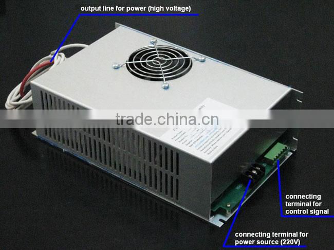
1) The positive red - line with high voltage is connected to the laser tail
2) The negative white - line is connected to laser output window
IV. Current limitation
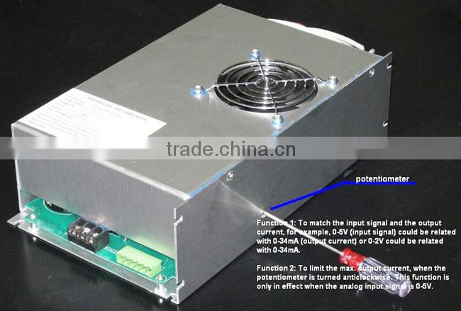
To limit the working current, the potentiometer (Lies in the underside of the power supply / power source should be rotated in counterclockwise (Please refer to the schematic diagram in our website). Limit the maximum output current as it is regulated in the operating instruction. The working current should be limited before delivery.
V. Linear scale between input signal and the output current
Turn around the potentiometer; the linear scale will be changed: for example, when the input signal is 0 - 5V, the output current is 0 - 32mA.Or when the input signals 0 - 2V, the output signal is 0 - 32mA.
Note: When the potentiometer is turned down too much, the real output current will be brought down by the same input signal.
VI. Using current
The use standard for our power supply / power source is under 110V, 60Hz. The fluctuation of the input voltage and frequency will affect the working current provided by the power supply / power source, the impact is linear relative. The unstable of the input voltage will affect the output power of the laser tube. The fluctuation of the input voltage has no impact on the lifespan of the laser if only the current provided by the supply / power source is not over the current limitation.

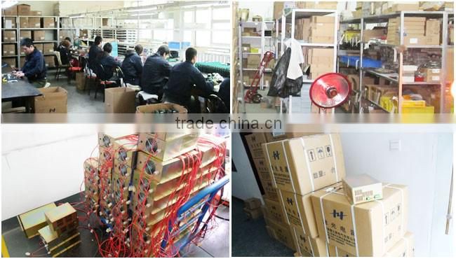
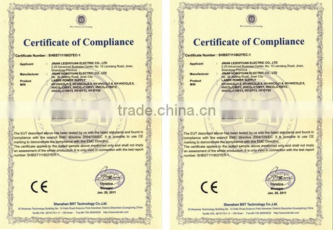
Quality Report:
Recommended Products
Recently Viewed
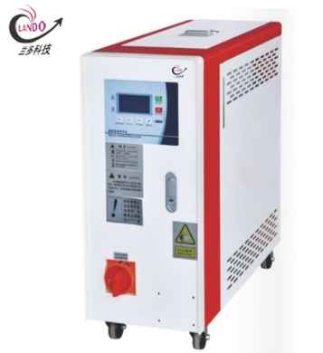 Lando Mold Temperature Controller Unit 12KW Cooling capacity
 Lando Ice Bath Cooling Unit & lando Ice Bath Chillers 3500W - 8800W
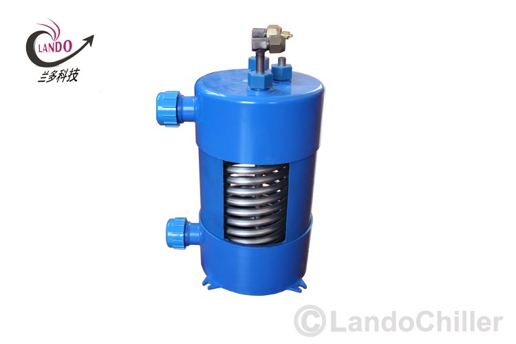 lando Heat Exchangers for Laser Chillers Titanium Heat Exchangers for Chemical - Industrial Water Chillers
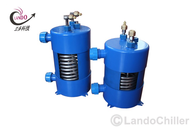 Lando Chiller unit titanium evaporator is widely used for mariculture ,Industrial chiller, laser chiller
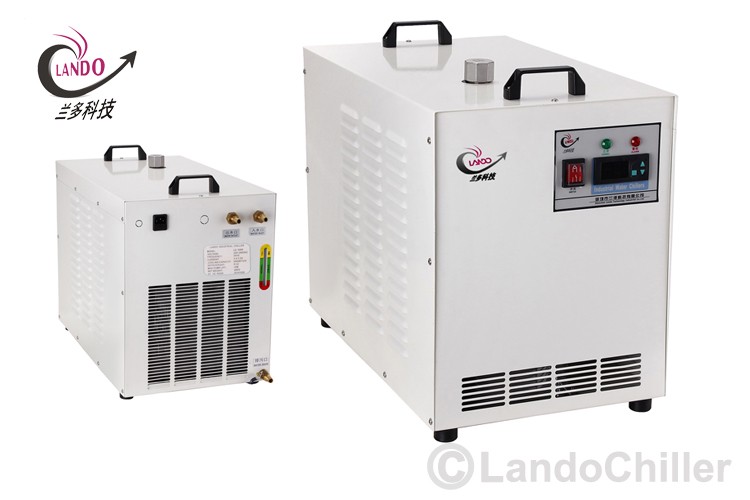 Lando Portable Industrial Water Chillers Cooling Systems for 130W-150W CO2 Glass Laser Tube
Contact Us
Beijing Chinasigns Information Co., Ltd.


